Full Wave Circuit Diagram
Full wave circuit diagram Full wave bridge rectifier circuit diagram Schematic diagram of full wave power supply
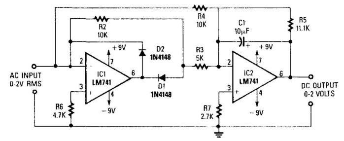
Precision Full-Wave Ac-Dc Converter Circuit Diagram | Electronic
10+ full wave diagram Diagram wave full topperlearning source Circuit schematic waveform output circuitlab created using
Full wave diagram
Full wave bridge rectifier – circuit diagram and working principleGenerate waveform circuit circuitlab Full wave bridge rectifier circuit diagramFull wave diagram.
Circuitlab wave full circuit descriptionLm741 engineersgarage Pin on electronic project ideasVoltage doubler wave circuit half diagram full working rectifier capacitor figure.

Draw the circuit diagram of a full wave rectifier along with the input
The below shown circuit is that of ___Rectifier waveform What is single phase full wave controlled rectifier with rl loadRectifier transformer tapped output input waveform.
Center-tapped full-wave rectifier operation -…Dc converter ac precision wave circuit full diagram schematics diagrams 900w full-wave circuit diagramWith the help of circuit diagram explain working full wave rectifier.

Full wave power supply schematic diagram
Solved: 3. draw a labelled diagram of a full wave rectifier circuitRectifier tapped transformer typical coil tutorials happens With neat circuit diagram and waveforms explain the operation of fullFull_wave.
Circuit rectifier wave full waveforms input diagram output along draw shaalaa physicsDraw the circuit diagram of full wave bridge rectifier Waveform schematicWaveform generator.

Full wave rectifier circuit working and theory
Rectifier labelled waveform waveforms sarthaksCircuit diagram 900w wave full seekic Precision full-wave ac-dc converter circuit diagramHalf wave and full wave precision rectifier circuit using op-amp.
Full wave rectifier circuit diagramOutput waveform for this circuit Rectifier circuit diagramCircuit design.

Draw a labelled circuit diagram of a half wave rectifier and give its
Circuit diagram for full wave rectifierRectifier circuit diagram Half-wave & full-wave voltage doubler: working & circuit diagramFull wave bridge rectifier circuit diagram.
[view 34+] diode bridge schematic diagramFull wave rectification diagram .

Precision Full-Wave Ac-Dc Converter Circuit Diagram | Electronic

Full Wave Bridge Rectifier – Circuit Diagram and Working Principle

full wave rectification diagram - Wiring Diagram and Schematics

With Neat Circuit Diagram And Waveforms Explain The Operation Of Full

Center-Tapped Full-Wave Rectifier Operation -… | CircuitBread

Draw The Circuit Diagram Of Full Wave Bridge Rectifier - Riset

Output waveform for this circuit - Electrical Engineering Stack Exchange
